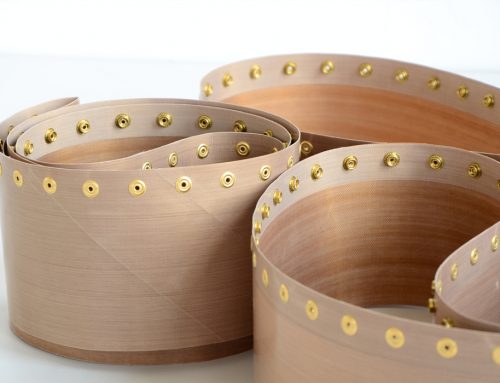
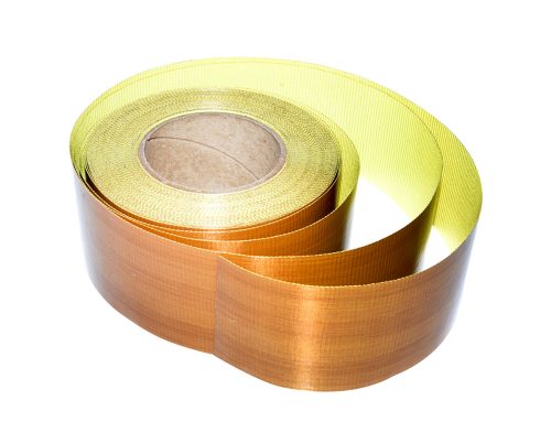
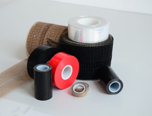
Car interior pieces including the car roof and interior carpet, its production line as Figure 1 by shows, which conveying track part used special fluoride Dragon with form, car roof and car carpet by with material for GFP Board or MA felt board, size: 2650mm*1700mm (long * wide), weight 900~1400g or 1500~1900 a, transfer device maximum transfer trip 7200mm, transfer speed range: 300~600 mm/s, it guarantee transfer device stable speed 500 mm/s. Teflon transmission requires dynamic stability, large power, carrying load adaptability is strong, and can be applied to high temperature working environment.
The line high speed feeding system adopts chain drive, not Teflon belt transmitting power. Due to chain drive inherent in the polygon effect, will make an impact on chains and sprockets, vibrate and periodic variation of speed and noise, it will affect the chain drive and big implications for the normal production.
In order to study the polygon effect of chain drive that Teflon belts work, determining their impact factor, aiming at the sprockets and chain gearing mechanisms, modeling and simulation with SolidWorks software, can directly reflect the movement of the chain, finally into ADAMS for simulation, simulation results can be used in Teflon belt optimized design of chain drive.
Polygon effect
As shown in Figure 2, chain and sprocket contacts could not completely meet the sprocket pitch trajectory.
From a geometrical point of view, positioning sprocket radius R, chain and sprocket after chain angle θ from a match turned, theory of displacement as: St= Rθ
Wheel rotation actually make up circular motion meshing with the chord movements alternating movements, chain movement phase linear displacement is equal to the string on the sprocket pitch cogging chord length, namely: Sf= 2sinθ/2R
The deviation of St and Sf is defined as ΔX=St-Sf.
This phenomenon is the chain drive sprocket polygon effect.
Chain sprocket Assembly modeling and motion simulation
Chain uses 16A double row of chain and the size standards adopted GB/T1243-1997, the chain track by automobile roof line, teflon conveyor belt slewing mechanism as a template, assembly molding.
Using SolidWorks to create whole body trajectory model (see Figure 3a). In order to simplify the model, set up Rotary sprocket pitch 98.13mm-Agency, inner-60.96mm. Swivel included both 180 ° and 90 °.
Finally build constraint for add drive sprocket wheel, keep the sprocket angular velocity is 10 ° / s, the movement simulation results was observed.
When the number of sprocket teeth less than 13, asymmetry and carries the load of the movement increased, as shown in Figure 4, the sprocket tooth number 12 when the dynamic load effects significantly greater than 15 of the sprocket teeth transmission. Gear transmission ratio unchanged when greater than 25 cases structure overall size is too large, do not conform to the actual application. Sprocket chain motion non-uniformity besides is directly related to the sprocket teeth, also is related to the sprocket center distance.
In order to analyze in detail the change of the load effect of the polygon effect in chain drive,the detailed data model is established, the above established SolidWorks model is simplified to single driving wheel driven wheel drive, the chain still USES 16 a double row of chain structure (as shown in figure 5).Due to the complexity of chain transmission model, kinematic and dynamic analysis was carried out on the chain, to simplify the analysis model. To simplify the SolidWorks model definition, processing with imported ADAMS software.
ADAMS polygon effect analysis
Chain drive model simplification and assumption
Teflon conveyor belt with chain drive of this paper is very complex, it is difficult to direct modeling in dynamic simulation software ADAMS, so using SolidWorks models have become a Parasolid file and then transfer to ADAMS. In the Parasolid file transfer process, the model information is lost (such as datum points and Datum coordinate systems, and so on). In addition, the simulation must be all new Marker in ADAMS, while dealing with a contact problem between the entity and entities, directly using SolidWorks models will be complex and long simulation time. Due to too many links, define the spin pair and contact one by one, will use a simplified chain model (see Figure 5).
According to the different location of interaction between link and sprocket, it is divided into three regions as shown in figure 6, and model reduction. Due to region a chain sprocket tooth contact at first, will have a relative velocity, resulting in a larger impact and dynamic load, and the contact force is relatively large. This part link have most influence on the dynamic characteristics of the system, it cannot be simplified. In area B, chain and sprockets continuous contact, in the steady-state phase, should be simplified. Regional chains in the C section, contact force is small, it also simplified.
To speed up the simulation process in ADAMS simulation model considers only rotating friction between the chain and does not take into account other friction, skidding and air resistance, and so on. The simulation results show: dynamic characteristics of simplified models in the analysis remain essentially the same as the original model, this model is reasonable. The model effect of ADAMS as shown in Figure 7.
Simulation results analysis
Figure 7 shows the model simulation analysis, Figure 8 describe a changes curve that a chain section from tight side NIE into to NIE out active round process in the contact force, it reflect superior contact force which only in near tight side of several chain section, chain section of location more near Pine side is contact force more small and reduced range is big, while showed that model simplified reasonable.
Here in the center line of the chain lower rate to measure the amount of fluctuation in sprocket and chain polygon effect of reduction is:
η=λ-ζ/λ*100%
In the formula: λ=p/2(1/sin(z/π))-(1/tan(z/π)),ζ is actual volatility, p is chain pitch.
Figure 9 respectively traditional linear tooth profile sprocket drive wheel in three critical speed 5 ° / s, 10 ° / s, 15 ° / s chain plate center of vertical center line change curve.
Figure 9 shows that changing chain plate center, in a fluctuating state, by observing the center of the chain plate can get chain fluctuation changed circumstances. Figure 10 depicts the 1 ~ 15 ° / s chain fluctuation quantity change trend.
Figure 11 is when 5 ° / s and 15 ° / s,the over time variation diagram of two drive meshing impact results.
When the tooth profile of the sprocket is different, the magnitude of the meshing impact force also changes. Figure 12 shows that, with the increasing of speed, increasing the impact between the chain and sprocket.
Conclusion
Teflon conveyor belt is studied in this paper with a chain of citations, the structure design and calculation of chain drive, primarily chain and sprocket selection, etc. In accordance with the chain transmission structure and components in SolidWorks establish digital model, and analyze the polygon effect theory. Finally will simplify the SolidWorks model into ADAMS, modeling, add motion pair and get after motion dynamics simulation model, simulation results help chain polygon effect after optimization design. Commonly used composite tooth profile sprocket, etc to minimize driven wheel angular velocity fluctuations, reduce the polygon effect.


